Skip to content

DWGSee CAD Support

  • Articles
  • User Guide
DWGSee CAD Support

What's New

6
  • New Features in DWGSee CAD 2027
    • Extract Dim
    • SCRIPT
    • UNION(Command)
    • SUBTRACT (Command)
    • MASSPROP
    • Rename

Get Started

4
  • Command Line List
  • Main Features
  • System Requirements
  • Welcome to DWGSee CAD

Have You Tried?

5
  • Isolate Objects
  • How to use Design Center in DWGSee CAD
  • How to merge lines/arcs to one ployline
  • How to Draw Arrows in DWGSee CAD
  • How to Select Objects Based on Shared Properties?

User Guide

69
  • Manage Drawing Files
    • ISOLATEOBJECTS (Command)
    • UNISOLATEOBJECTS (Command)
    • HIDEOBJECTS (Command)
    • Units
    • Create a new drawing
  • Create Objects
    • BLEND
    • Hatch
    • Ellipse
    • Circle
    • Multiline
    • Spline
    • Point
    • XLINE
    • UNION(Command)
    • SUBTRACT (Command)
    • INTERSECT(Command)
    • Arc
    • Rectangle
    • Polygon
    • Polyline
    • Line
    • Create Text
      • STYLE
    • Create Curved and Closed Geometry
      • About Donuts
        • Donut
      • About Regions
        • Region
    • Create Linear and Reference Geometry
      • TangentLine
  • Reference External Files and Data
    • DWFATTACH
  • Defining Blocks
    • WBLOCK
    • About Purging Unreferenced Layers, Blocks, and Style Definitions
      • PURGE
  • Modify Objects
    • CHAMFER
    • EXTEND
    • TRIM
    • Pedit
    • Mledit
    • Fillet
    • Copy
    • Scale
    • Array
    • Mirror
    • PURGE
    • Duplicate and Array Objects
      • Offset
      • About Copying Objects
        • NCOPY(Command)
    • Remove Objects and Object Segments
      • Erase
      • Break
      • Join
      • About Correcting Mistakes
        • Overkill
        • OOPS
    • Change General Object Properties
      • Linetype
      • Layer
      • How to Change the Color of Selected Objects?
      • LIST
      • About Object Properties
        • MATCHPROP
    • Editing Complex Objects
      • EDITTOL
      • EXPLODE
    • Change the Size and Length of Objects
      • Lengthen
      • EXTEND
      • TRIM
    • Move and Rotate Objects
      • Align
      • Rotate
      • Stretch
      • Move
  • Control Drawing Views
    • REGEN
    • ZOOM
    • PAN
  • Control Precision with Drafting Aids
    • LIMITS (Command)
  • Add Hatches, Fills, Tables, and Revision Clouds
    • Wipeout
  • Create Notes, Labels, and Leaders
    • Extract Dim
    • ANNOALLVISIBLE (System Variable)
  • Dimension Objects
    • TOLERANCE
    • CenterLine

License

1
  • End-User License Agreement
View Categories
  • DWGSee CAD
  • Support
  • User Guide
  • Reference External Files and Data
  • DWFATTACH

DWFATTACH

You can attach a DWF, DWFx file as an underlay to a drawing file.

You can reference and place underlay files in drawing files the same way as you do raster image files; they are not actually part of the drawing file. Like raster files, the underlay is linked to the drawing file through a path name, which can be changed or removed at any time. However, you cannot bind an underlay to a drawing and you cannot edit or modify the underlay’s content.

By attaching dwf, you can access files in your drawing without greatly increasing the drawing file size.

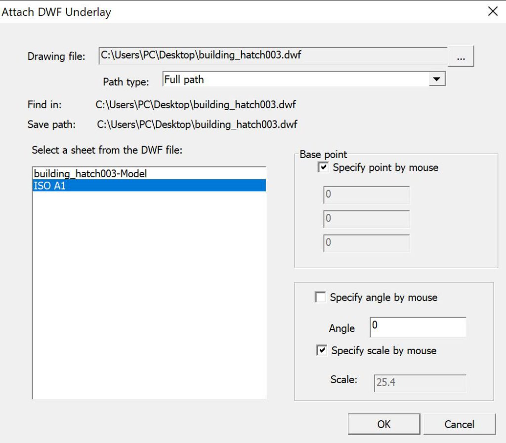
  • Command line enter “DWFAttach” or Click Menu “Insert/DWF Underlay”
  • In the Select Reference File dialog box, select the file you want to attach.
  • Click Open.
  • In the Attach DWF Underlay dialog box, select one sheet, or select multiple sheets.
  • Use one of the following methods to specify the insertion point, scale, or rotation of the underlay file:
  • Select Specify On-Screen to use the pointing device to attach the DWF underlay at the location, scale, or angle you want.
  • Clear Specify On-Screen and enter values under Insertion Point, Scale, or Rotation.
  • Click OK.
Command Line, DWF, Underlays
Share This Article :
  • Facebook
  • X
  • LinkedIn
  • Pinterest

© 2026 DWGSee CAD Support

  • Articles
  • User Guide