You can create copies of objects in a rectangular or polar (circular) pattern called an array.
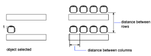
For rectangular arrays, you control the number of rows and columns and the distance between each. For polar arrays, you control the number of copies of the object and whether the copies are rotated. To create many regularly spaced objects, arraying is faster than copying.
Create Rectangular Arrays #
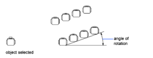
A rectangular array is built along a baseline defined by the current snap rotation angle. This angle is zero by default, so the rows and columns of a rectangular array are orthogonal with respect to the X and Y axes.
- Click Modify» Array or Command line Array
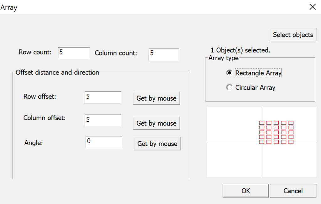
- In the Array dialog box, select Rectangular Array.
- Click Select Objects.
- The Array dialog box closes. You are prompted for object selection.
- Select the objects to be arrayed and press ENTER.
- In the Rows and Columns boxes, enter the number of rows and columns in the array.
- Specify the horizontal and vertical spacing (offsets) between objects by using one of the following methods:
- In the Row Offset and Column Offset boxes, enter the distance between rows and between columns. Adding a plus sign (+) or a minus sign (-) determines direction.
- Click the Pick Both Offsets button to use the pointing device to specify the diagonal corners of a cell in the array. The cell determines the vertical and horizontal spacing of the rows and columns.
- Click the Pick Row Offset or Pick Column Offset button to use the pointing device to specify the horizontal and vertical spacing.
- To change the rotation angle of the array, enter the new angle next to Angle of Array.
- Click OK to create the array.
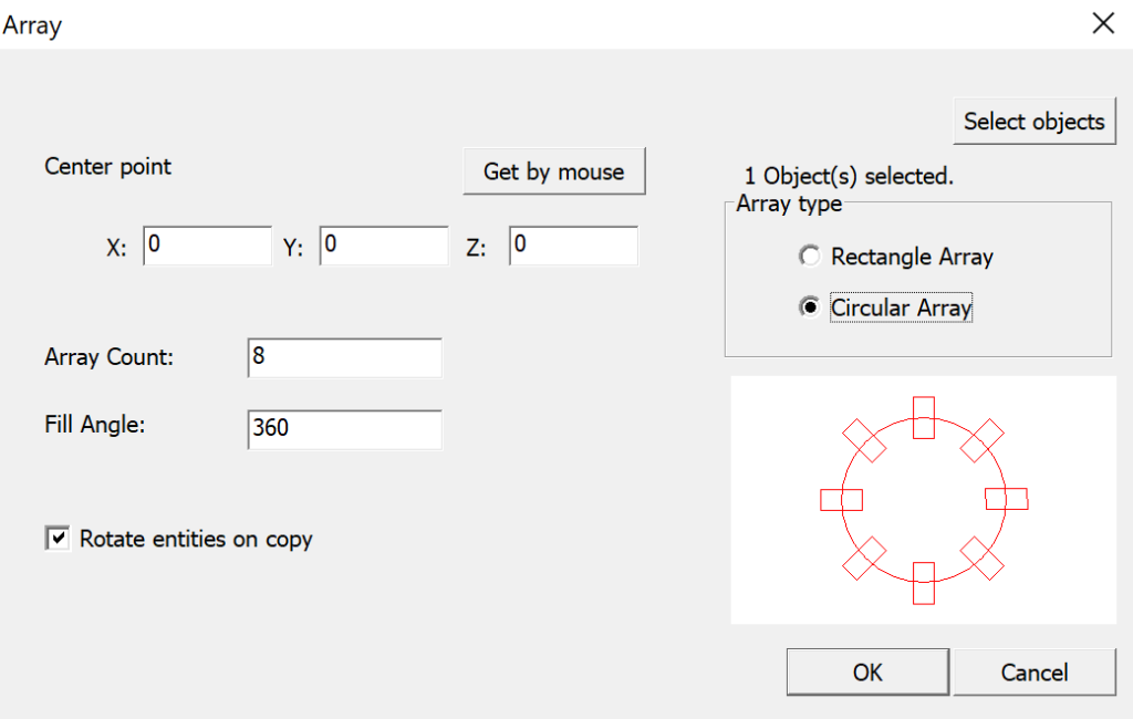
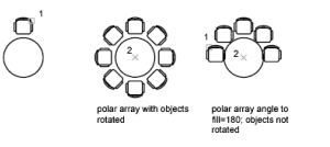
Create Polar Arrays #
When you create a polar array, the array is drawn counterclockwise or clockwise, depending on whether you enter a positive or a negative value for the angle to fill.
The radius of the array is determined by the distance from the specified center point to a reference or base point on the last selected object. You can use the default reference point (usually an arbitrary point that coincides with a snap point), or you can specify a new base point to be used as the reference point.
- Click Modify » Array or Command line enter Array
- In the Array dialog box, select Polar Array.
- Next to Center Point, do one of the following:
Enter an X value and a Y value for the center point of the polar array.
Click the Pick Center Point button. The Array dialog box closes and you are prompted for object selection. Use the pointing device to specify the center point of the polar array. - Click Select Objects.
The Array dialog box closes and you are prompted for object selection. - Select the objects to be arrayed.
- Enter the number of items (including the original object).
- Enter the angle to fill and angle between items.
- To rotate the objects as they are arrayed, select Rotate Items As Copied.
- Click OK to create the array.