Edits multiline intersections, breaks, and vertices.
The Multiline Edit Tools dialog box is displayed.
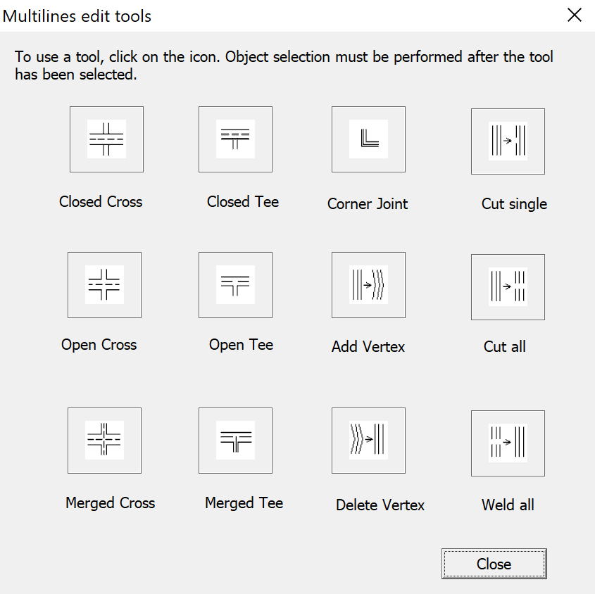
The dialog box displays tools with sample images in four columns. The first column controls multilines that cross, the second controls multilines that form a tee, the third controls corner joints and vertices, and the fourth controls breaks in multilines.
List of Options #
The following options are displayed.
Closed Cross #

Creates a closed-cross intersection between two multilines.
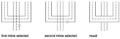
- Select First Mline. Select the foreground multiline
- Select Second Mline. Select the intersecting multiline.
Open Cross #

Creates an open-cross intersection between two multilines. Breaks are inserted in all elements of the first multiline and only the outside elements of the second multiline.
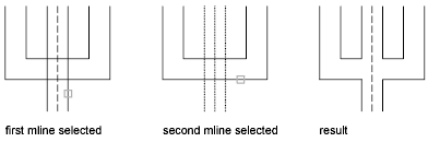
- Select First Mline. Select a multiline
- Select Second Mline. Select the intersecting multiline.
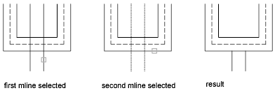
Merged Cross #

Creates a merged-cross intersection between two multilines. The order in which you select the multilines is not important.

- Select First Mline.
- Select Second Mline.
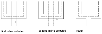
Closed Tee #

Creates a closed-tee intersection between two multilines. The first multiline is trimmed or extended to its intersection with the second multiline.
- Select First Mline.
- Select Second Mline.
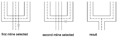
Open Tee #

Creates an open-tee intersection between two multilines. The first multiline is trimmed or extended to its intersection with the second multiline.
- Select First Mline.
- Select Second Mline.
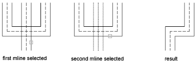
Merged Tee #

Creates a merged-tee intersection between two multilines.The multiline is trimmed or extended to its intersection with the other multiline.
- Select First Mline.
- Select Second Mline.
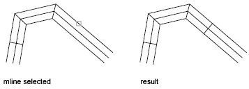
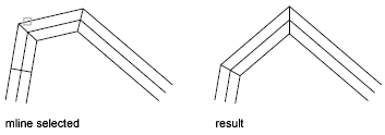
Corner Joint #

Creates a corner joint between multilines. The multilines are trimmed or extended to their intersection.
- Select First Mline.
- Select Second Mline.
Add Vertex #

Adds a vertex to a multiline.
- Select Mline. Select the multiline at the point that you want to add the vertex.
Delete Vertex #

Deletes a vertex from a multiline.
- Select Mline. The vertex nearest to the selected point is deleted.
Cut Single #

Creates a visual break in a selected element of a multiline.
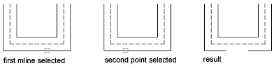
- Select Mline. The selection point on the multiline is used as the first cut point.
- Select Second Point. Specify the second cut point on the multiline.
Cut All #

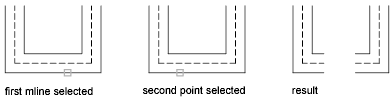
Creates a visual break through the entire multiline.
- Select Mline.
- Select Second Point.
Weld All #

Rejoins multiline segments that have been cut.
- Select Mline. The selection point on the multiline is used as the start of the weld.
- Select Second Point. Specify the end of the weld on the multiline.


