Skip to content

DWGSee CAD Support

    DWGSee CAD Support

    What's New

    5
    • New Features in DWGSee CAD 2026
      • SCRIPT
      • UNION(Command)
      • SUBTRACT (Command)
      • MASSPROP
      • Rename

    Get Started

    4
    • Command Line List
    • Main Features
    • System Requirements
    • Welcome to DWGSee CAD

    Have You Tried?

    6
    • Isolate Objects
    • Quick Select
    • How to use Design Center in DWGSee CAD
    • How to merge lines/arcs to one ployline
    • How to Draw Arrows in DWGSee CAD
    • How to Select Objects Based on Shared Properties?

    User Guide

    65
    • Manage Drawing Files
      • ISOLATEOBJECTS (Command)
      • UNISOLATEOBJECTS (Command)
      • HIDEOBJECTS (Command)
      • Units
      • Create a new drawing
    • Create Objects
      • BLEND
      • Hatch
      • Ellipse
      • Circle
      • Multiline
      • Spline
      • Point
      • XLINE
      • UNION(Command)
      • SUBTRACT (Command)
      • INTERSECT(Command)
      • Arc
      • Rectangle
      • Polygon
      • Polyline
      • Line
      • Create Text
        • STYLE
      • Create Curved and Closed Geometry
        • About Donuts
          • Donut
        • About Regions
          • Region
      • Create Linear and Reference Geometry
        • TangentLine
    • Reference External Files and Data
      • DWFATTACH
    • Defining Blocks
      • WBLOCK
      • About Purging Unreferenced Layers, Blocks, and Style Definitions
        • PURGE
    • Modify Objects
      • CHAMFER
      • EXTEND
      • TRIM
      • Pedit
      • Mledit
      • Fillet
      • Copy
      • Scale
      • Array
      • Mirror
      • PURGE
      • Duplicate and Array Objects
        • Offset
        • About Copying Objects
          • NCOPY(Command)
      • Remove Objects and Object Segments
        • Erase
        • Break
        • Join
        • About Correcting Mistakes
          • Overkill
          • OOPS
      • Change General Object Properties
        • Linetype
        • Layer
        • How to Change the Color of Selected Objects?
        • LIST
      • Editing Complex Objects
        • EXPLODE
      • Change the Size and Length of Objects
        • Lengthen
        • EXTEND
        • TRIM
      • Move and Rotate Objects
        • Align
        • Rotate
        • Stretch
        • Move
    • Control Drawing Views
      • REGEN
      • ZOOM
      • PAN
    • Control Precision with Drafting Aids
      • LIMITS (Command)

    License

    1
    • End-User License Agreement
    View Categories
    • DWGSee CAD
    • Support
    • User Guide
    • Modify Objects
    • CHAMFER

    CHAMFER

    A chamfer or bevel connects two objects with an angled line in 2D

    You can create a chamfer or bevel using the CHAMFER command

    And you also can use CHAMFER2 to create.

    Length and Angle of a Chamfer #

    A chamfer can be defined using one of two methods; distance or angle. The current method to define a chamfer or bevel is set with the Method option.

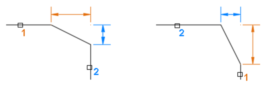
    • Distance. The resulting angled line is based on two distance values. The distance values are used to trim or extend the selected objects to meet the resulting angled line. The first distance value affects the first object selected, while the second distance value affects the second object selected.
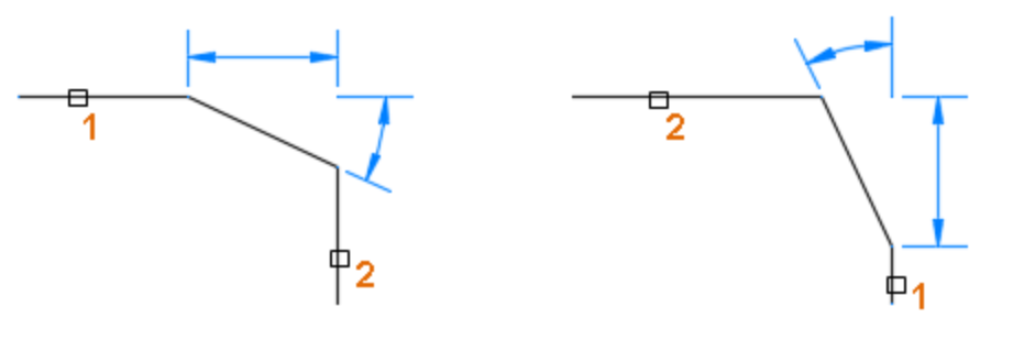
    • Angle. The resulting angled line is based on a distance and an angle value. The distance and angular value are used to trim or extend the selected objects to meet the resulting angled line. The distance value directly affects the first object selected.

    Note: If the distance and angle values are set to 0, the selected objects are trimmed or extended until they intersect and no angled line is created.

    Create a Chamfer Defined by a Length and an Angle #

    The size of the chamfer is defined by a length and an angle. The length value defines the first side of the chamfer from the intersection of the two selected objects or adjacent 2D polyline segments, and the angle value defines the second side of the chamfer.

    1. Click Modify/Chamfer
    2. At the Command prompt, enter a (Angle).
    3. Enter a new chamfer length on the first line.
    4. Enter a new chamfer angle from the first line.
    5. Enter e (mEthod) and then enter a (Angle).
    6. In the drawing area, select the first object or adjacent line segment in a 2D polyline. Note: You can select a line, ray, or xline.
    7. Select the second object or an adjacent line segment in the 2D polyline. Note: If the second line segment selected isn’t adjacent to the first line segment, the line segments between the selected segments are removed and replaced with the chamfer.

    Create a Chamfer Defined by Two Distances #

    The size of the chamfer distance is defined by two length values. The length values define the first and second sides of the chamfer from the intersection of the two selected objects or adjacent 2D polyline segments.

    1. Click Modify/Chamfer. 
    2. At the Command prompt, enter d (Distance).
    3. Enter a new first chamfer distance.
    4. Enter a new second chamfer distance.
    5. Enter e (mEthod) and then enter d (Distance).
    6. In the drawing area, select the first object or adjacent line segment in a 2D polyline. Note: You can select a line, ray, or xline.
    7. Select the second object or an adjacent line segment in the 2D polyline. Note: If the second line segment selected isn’t adjacent to the first line segment, the line segments between the selected segments are removed and replaced with the chamfer.

    Chamfer Lines or Line Segments Without Trimming #

    1. Click Modify/Chamfer. 
    2. At the Command prompt, enter t (Trim).
    3. Enter n (No Trim).
    4. In the drawing area, select the objects or adjacent line segments in a 2D polyline.
    Chamfer, Command Line
    Share This Article :
    • Facebook
    • X
    • LinkedIn
    • Pinterest
    Table of Contents
    • Length and Angle of a Chamfer
    • Create a Chamfer Defined by a Length and an Angle
    • Create a Chamfer Defined by Two Distances
    • Chamfer Lines or Line Segments Without Trimming

    © 2025 DWGSee CAD Support