Skip to content

DWGSee CAD Support

    DWGSee CAD Support

    What's New

    5
    • New Features in DWGSee CAD 2026
      • SCRIPT
      • UNION(Command)
      • SUBTRACT (Command)
      • MASSPROP
      • Rename

    Get Started

    4
    • Command Line List
    • Main Features
    • System Requirements
    • Welcome to DWGSee CAD

    Have You Tried?

    6
    • Isolate Objects
    • Quick Select
    • How to use Design Center in DWGSee CAD
    • How to merge lines/arcs to one ployline
    • How to Draw Arrows in DWGSee CAD
    • How to Select Objects Based on Shared Properties?

    User Guide

    65
    • Manage Drawing Files
      • ISOLATEOBJECTS (Command)
      • UNISOLATEOBJECTS (Command)
      • HIDEOBJECTS (Command)
      • Units
      • Create a new drawing
    • Create Objects
      • BLEND
      • Hatch
      • Ellipse
      • Circle
      • Multiline
      • Spline
      • Point
      • XLINE
      • UNION(Command)
      • SUBTRACT (Command)
      • INTERSECT(Command)
      • Arc
      • Rectangle
      • Polygon
      • Polyline
      • Line
      • Create Text
        • STYLE
      • Create Curved and Closed Geometry
        • About Donuts
          • Donut
        • About Regions
          • Region
      • Create Linear and Reference Geometry
        • TangentLine
    • Reference External Files and Data
      • DWFATTACH
    • Defining Blocks
      • WBLOCK
      • About Purging Unreferenced Layers, Blocks, and Style Definitions
        • PURGE
    • Modify Objects
      • CHAMFER
      • EXTEND
      • TRIM
      • Pedit
      • Mledit
      • Fillet
      • Copy
      • Scale
      • Array
      • Mirror
      • PURGE
      • Duplicate and Array Objects
        • Offset
        • About Copying Objects
          • NCOPY(Command)
      • Remove Objects and Object Segments
        • Erase
        • Break
        • Join
        • About Correcting Mistakes
          • Overkill
          • OOPS
      • Change General Object Properties
        • Linetype
        • Layer
        • How to Change the Color of Selected Objects?
        • LIST
      • Editing Complex Objects
        • EXPLODE
      • Change the Size and Length of Objects
        • Lengthen
        • EXTEND
        • TRIM
      • Move and Rotate Objects
        • Align
        • Rotate
        • Stretch
        • Move
    • Control Drawing Views
      • REGEN
      • ZOOM
      • PAN
    • Control Precision with Drafting Aids
      • LIMITS (Command)

    License

    1
    • End-User License Agreement
    View Categories
    • DWGSee CAD
    • Support
    • User Guide
    • Create Objects
    • Ellipse

    Ellipse

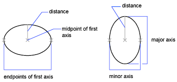
    When you draw an ellipse, its shape is determined by two axes that define its length and width: the major (longer) axis and the minor (shorter) axis.

    Axis Endpoint #

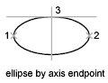
    Defines the first axis by its two endpoints. The angle of the first axis determines the angle of the ellipse. The first axis can define either the major or the minor axis of the ellipse.

    Distance to Other Axis #

    Defines the second axis using the distance from the midpoint of the first axis to the endpoint of the second axis (3).

    Rotation #

    Creates the ellipse by appearing to rotate a circle about the first axis.

    Move the crosshairs around the center of the ellipse and click. If you enter a value, the higher the value, the greater the eccentricity of the ellipse. Entering 0 defines a circular ellipse.

    Arc #

    Creates an elliptical arc.

    The angle of the first axis determines the angle of the elliptical arc. The first axis can define either the major or the minor axis depending on its size.

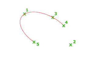
    The first two points of the elliptical arc determine the location and length of the first axis. The third point determines the distance between the center of the elliptical arc and the endpoint of the second axis. The fourth and fifth points are the start and end angles.

    Axis Endpoint #

    Defines the start point of the first axis.

    Rotation #

    Defines the major to minor axis ratio of the ellipse by rotating a circle about the first axis. The higher the value from 0 through 89.4 degrees, the greater the ratio of minor to major axis. Values between 89.4 degrees and 90.6 degrees are invalid because the ellipse would otherwise appear as a straight line. Multiples of these angle values result in a mirrored effect every 90 degrees.

    Start Angle #

    Defines the first endpoint of the elliptical arc. The Start Angle option also changes Parameter mode to Angle mode. The mode controls how the ellipse is calculated.
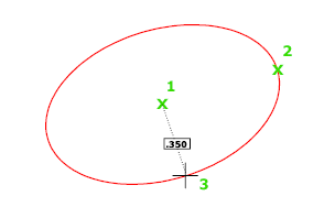
    Center #

    Creates an ellipse using a center point, the endpoint of the first axis, and the length of the second axis. You can specify the distances by clicking a location at the desired distance or by entering a value for the length.

    Distance to Other Axis #

    Defines the second axis as the distance from the center of the ellipse, or midpoint of the first axis, to the point you specify.

    Rotation #

    Creates the ellipse by appearing to rotate a circle about the first axis.

    Move the crosshairs around the center of the ellipse and click. If you enter a value, the higher the value, the greater the eccentricity of the ellipse. Entering 0 defines a circle.

    ELLIPSE
    Share This Article :
    • Facebook
    • X
    • LinkedIn
    • Pinterest
    Table of Contents
    • Axis Endpoint
    • Distance to Other Axis
    • Rotation
    • Arc
      • Axis Endpoint
      • Rotation
      • Start Angle
    • Center
      • Distance to Other Axis
      • Rotation

    © 2025 DWGSee CAD Support