Skip to content

DWGSee CAD Support

    DWGSee CAD Support

    What's New

    5
    • New Features in DWGSee CAD 2026
      • SCRIPT
      • UNION(Command)
      • SUBTRACT (Command)
      • MASSPROP
      • Rename

    Get Started

    4
    • Command Line List
    • Main Features
    • System Requirements
    • Welcome to DWGSee CAD

    Have You Tried?

    6
    • Isolate Objects
    • Quick Select
    • How to use Design Center in DWGSee CAD
    • How to merge lines/arcs to one ployline
    • How to Draw Arrows in DWGSee CAD
    • How to Select Objects Based on Shared Properties?

    User Guide

    65
    • Manage Drawing Files
      • ISOLATEOBJECTS (Command)
      • UNISOLATEOBJECTS (Command)
      • HIDEOBJECTS (Command)
      • Units
      • Create a new drawing
    • Create Objects
      • BLEND
      • Hatch
      • Ellipse
      • Circle
      • Multiline
      • Spline
      • Point
      • XLINE
      • UNION(Command)
      • SUBTRACT (Command)
      • INTERSECT(Command)
      • Arc
      • Rectangle
      • Polygon
      • Polyline
      • Line
      • Create Text
        • STYLE
      • Create Curved and Closed Geometry
        • About Donuts
          • Donut
        • About Regions
          • Region
      • Create Linear and Reference Geometry
        • TangentLine
    • Reference External Files and Data
      • DWFATTACH
    • Defining Blocks
      • WBLOCK
      • About Purging Unreferenced Layers, Blocks, and Style Definitions
        • PURGE
    • Modify Objects
      • CHAMFER
      • EXTEND
      • TRIM
      • Pedit
      • Mledit
      • Fillet
      • Copy
      • Scale
      • Array
      • Mirror
      • PURGE
      • Duplicate and Array Objects
        • Offset
        • About Copying Objects
          • NCOPY(Command)
      • Remove Objects and Object Segments
        • Erase
        • Break
        • Join
        • About Correcting Mistakes
          • Overkill
          • OOPS
      • Change General Object Properties
        • Linetype
        • Layer
        • How to Change the Color of Selected Objects?
        • LIST
      • Editing Complex Objects
        • EXPLODE
      • Change the Size and Length of Objects
        • Lengthen
        • EXTEND
        • TRIM
      • Move and Rotate Objects
        • Align
        • Rotate
        • Stretch
        • Move
    • Control Drawing Views
      • REGEN
      • ZOOM
      • PAN
    • Control Precision with Drafting Aids
      • LIMITS (Command)

    License

    1
    • End-User License Agreement
    View Categories
    • DWGSee CAD
    • Support
    • User Guide
    • Modify Objects
    • Move and Rotate Objects
    • Stretch

    Stretch

    Objects that are partially enclosed by a crossing window are stretched. Objects that are completely enclosed within the crossing window, or that are selected individually, are moved rather than stretched. Some types of objects such as circles, ellipses, and blocks, cannot be stretched.

    1. Command line enter Stretch/S, or Click Menu Modify/Stretch.
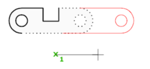
    2. Select the object using a crossing window selection.
    3. Do one of the following:
      Enter the displacement in the form of a relative Cartesian, polar, cylindrical, or spherical coordinate. Press Enter at the prompt for the second point of displacement.
      Or Specify the base point for the stretch, and then specify a second point, to determine the distance and direction.

    The following prompts are displayed.

    Select objects #

    Specifies the portion of the object that you want to stretch. Use the cpolygon option or the crossing object selection method. Press Enter when the selection is complete.

    STRETCH moves only the vertices and endpoints that lie inside the crossing selection, leaving those outside unchanged. STRETCH does not modify 3D solids, polyline width, tangent, or curve-fitting information.

    Base Point #

    Specifies the base point from which the offset for the stretch is calculated. This base point can be outside the area being stretched.

    Second point #

    Specifies a second point that defines the distance and direction of the stretch. The distance and direction of this point from the base point defines how far the and in what direction the selected portions of the object will be stretched.

    Use first point as displacement #

    Specifies that the stretch distance and direction will be based on the distance and direction of the base point you specified from the 0,0,0 coordinates in the drawing.

    Displacement #

    Specifies the relative distance and direction of the stretch.

    Command Line, Moving and Rotating Objects, Stretch
    Share This Article :
    • Facebook
    • X
    • LinkedIn
    • Pinterest
    Table of Contents
    • Select objects
    • Base Point
    • Second point
    • Use first point as displacement
    • Displacement

    © 2025 DWGSee CAD Support