Skip to content

DWGSee CAD Support

    DWGSee CAD Support

    What's New

    5
    • New Features in DWGSee CAD 2026
      • SCRIPT
      • UNION(Command)
      • SUBTRACT (Command)
      • MASSPROP
      • Rename

    Get Started

    4
    • Command Line List
    • Main Features
    • System Requirements
    • Welcome to DWGSee CAD

    Have You Tried?

    6
    • Isolate Objects
    • Quick Select
    • How to use Design Center in DWGSee CAD
    • How to merge lines/arcs to one ployline
    • How to Draw Arrows in DWGSee CAD
    • How to Select Objects Based on Shared Properties?

    User Guide

    68
    • Manage Drawing Files
      • ISOLATEOBJECTS (Command)
      • UNISOLATEOBJECTS (Command)
      • HIDEOBJECTS (Command)
      • Units
      • Create a new drawing
    • Create Objects
      • BLEND
      • Hatch
      • Ellipse
      • Circle
      • Multiline
      • Spline
      • Point
      • XLINE
      • UNION(Command)
      • SUBTRACT (Command)
      • INTERSECT(Command)
      • Arc
      • Rectangle
      • Polygon
      • Polyline
      • Line
      • Create Text
        • STYLE
      • Create Curved and Closed Geometry
        • About Donuts
          • Donut
        • About Regions
          • Region
      • Create Linear and Reference Geometry
        • TangentLine
    • Reference External Files and Data
      • DWFATTACH
    • Defining Blocks
      • WBLOCK
      • About Purging Unreferenced Layers, Blocks, and Style Definitions
        • PURGE
    • Modify Objects
      • CHAMFER
      • EXTEND
      • TRIM
      • Pedit
      • Mledit
      • Fillet
      • Copy
      • Scale
      • Array
      • Mirror
      • PURGE
      • Duplicate and Array Objects
        • Offset
        • About Copying Objects
          • NCOPY(Command)
      • Remove Objects and Object Segments
        • Erase
        • Break
        • Join
        • About Correcting Mistakes
          • Overkill
          • OOPS
      • Change General Object Properties
        • Linetype
        • Layer
        • How to Change the Color of Selected Objects?
        • LIST
        • About Object Properties
          • MATCHPROP
      • Editing Complex Objects
        • EDITTOL
        • EXPLODE
      • Change the Size and Length of Objects
        • Lengthen
        • EXTEND
        • TRIM
      • Move and Rotate Objects
        • Align
        • Rotate
        • Stretch
        • Move
    • Control Drawing Views
      • REGEN
      • ZOOM
      • PAN
    • Control Precision with Drafting Aids
      • LIMITS (Command)

    License

    1
    • End-User License Agreement
    View Categories
    • DWGSee CAD
    • Support
    • User Guide
    • Dimension Objects
    • TOLERANCE

    TOLERANCE

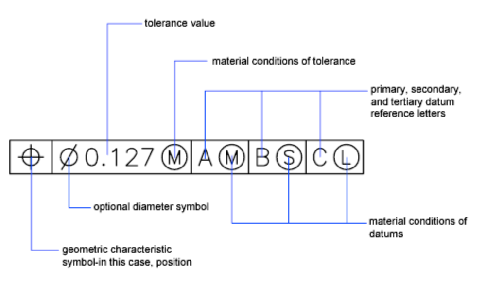
    Geometric tolerances show acceptable deviations of form, profile, orientation, location, and runout of a feature.

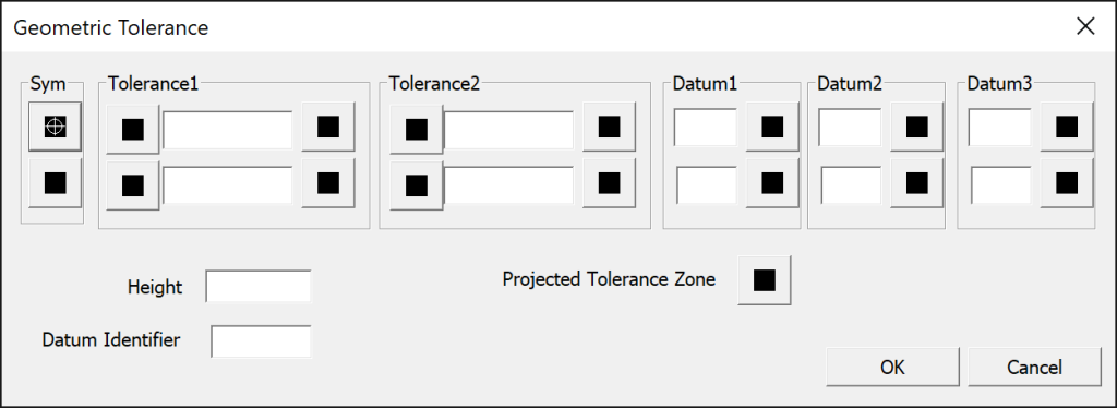
    1. Click Annotate/Geometric Tolerance.  
    2. In the Geometric Tolerance dialog box, click the first square under Sym and select a symbol to insert.
    3. Under Tolerance 1, click the first black box to insert a diameter symbol.
    4. In the Text box, enter the first tolerance value.
    5. To add a material condition (optional), click the second black box and click a symbol in the Material Conditions dialog box to insert it.
    6. In the Geometric Tolerance dialog box, add a second tolerance value (optional) in the same way as the first tolerance value.
    7. Under Datum 1, Datum 2, Datum 3, enter the datum reference letter.
    8. Click the black box to insert a material condition symbol for each datum reference.
    9. In the Height box, enter a height.
    10. Click the Projected Tolerance Zone box to insert the symbol.
    11. In the Datum Identifier box, add a datum value.
    12. Click OK.
    13. In the drawing, specify a location for the feature control frame.
    Command Line, Tolerance
    Share This Article :
    • Facebook
    • X
    • LinkedIn
    • Pinterest

    © 2025 DWGSee CAD Support