Skip to content

DWGSee CAD Support

    DWGSee CAD Support

    What's New

    5
    • New Features in DWGSee CAD 2026
      • SCRIPT
      • UNION(Command)
      • SUBTRACT (Command)
      • MASSPROP
      • Rename

    Get Started

    4
    • Command Line List
    • Main Features
    • System Requirements
    • Welcome to DWGSee CAD

    Have You Tried?

    6
    • Isolate Objects
    • Quick Select
    • How to use Design Center in DWGSee CAD
    • How to merge lines/arcs to one ployline
    • How to Draw Arrows in DWGSee CAD
    • How to Select Objects Based on Shared Properties?

    User Guide

    65
    • Manage Drawing Files
      • ISOLATEOBJECTS (Command)
      • UNISOLATEOBJECTS (Command)
      • HIDEOBJECTS (Command)
      • Units
      • Create a new drawing
    • Create Objects
      • BLEND
      • Hatch
      • Ellipse
      • Circle
      • Multiline
      • Spline
      • Point
      • XLINE
      • UNION(Command)
      • SUBTRACT (Command)
      • INTERSECT(Command)
      • Arc
      • Rectangle
      • Polygon
      • Polyline
      • Line
      • Create Text
        • STYLE
      • Create Curved and Closed Geometry
        • About Donuts
          • Donut
        • About Regions
          • Region
      • Create Linear and Reference Geometry
        • TangentLine
    • Reference External Files and Data
      • DWFATTACH
    • Defining Blocks
      • WBLOCK
      • About Purging Unreferenced Layers, Blocks, and Style Definitions
        • PURGE
    • Modify Objects
      • CHAMFER
      • EXTEND
      • TRIM
      • Pedit
      • Mledit
      • Fillet
      • Copy
      • Scale
      • Array
      • Mirror
      • PURGE
      • Duplicate and Array Objects
        • Offset
        • About Copying Objects
          • NCOPY(Command)
      • Remove Objects and Object Segments
        • Erase
        • Break
        • Join
        • About Correcting Mistakes
          • Overkill
          • OOPS
      • Change General Object Properties
        • Linetype
        • Layer
        • How to Change the Color of Selected Objects?
        • LIST
      • Editing Complex Objects
        • EXPLODE
      • Change the Size and Length of Objects
        • Lengthen
        • EXTEND
        • TRIM
      • Move and Rotate Objects
        • Align
        • Rotate
        • Stretch
        • Move
    • Control Drawing Views
      • REGEN
      • ZOOM
      • PAN
    • Control Precision with Drafting Aids
      • LIMITS (Command)

    License

    1
    • End-User License Agreement
    View Categories
    • DWGSee CAD
    • Support
    • User Guide
    • Add Hatches, Fills, Tables, and Revision Clouds
    • Wipeout

    Wipeout

    A wipeout object is a polygonal area that masks underlying objects with the current background color. The wipeout area is defined by the wipeout frame, which you can turn on for editing and turn off for plotting.

    Creates a polygonal area that masks underlying objects with the current background color. The wipeout area is bounded by a frame that you can turn on or off. You can also choose to display the frame on screen and have it hidden for plotting.

    Rectangle #

    Determines the rectangle boundary of the wipeout objects from a rectangle.
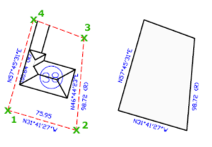
    Polyline #

    Determines the polygonal boundary of the wipeout objects from a selected polyline.

    First Point #

    Determines the boundary of the wipeout object from a series of points.

    Frames #

    Determines whether the edges of all wipeout objects are displayed or hidden.

    Available Frames modes:

    • ON – frames are displayed and plotted
    • OFF – frames are not displayed or plotted
    • Display but not plot – frames are displayed but are not plotted

    Using Wipeout Objects on a Layout #

    You can create wipeout objects on a layout in paper space to mask objects in model space. However, in the Page Settings dialog box, under Plot Options, the Plot Paper Space Last option must be cleared before you plot to ensure that the wipeout object is plotted correctly.

    Because a wipeout object is similar to a raster image, it has the same requirements for plotting. You need a raster-capable plotter with either an ADI 4.3 raster-capable driver or the system printer driver.

    Command Line, wipeout
    Share This Article :
    • Facebook
    • X
    • LinkedIn
    • Pinterest
    Table of Contents
    • Rectangle
    • Polyline
    • First Point
    • Frames
    • Using Wipeout Objects on a Layout

    © 2025 DWGSee CAD Support